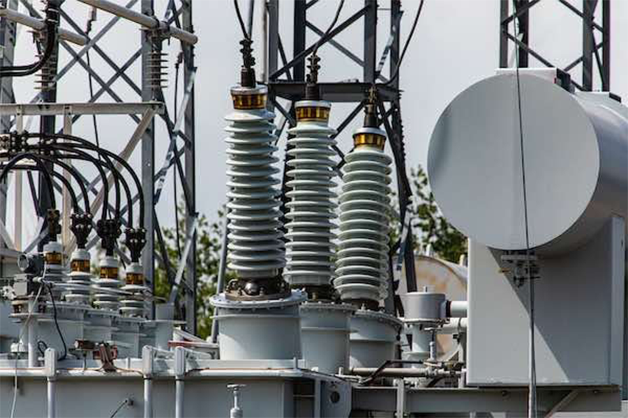
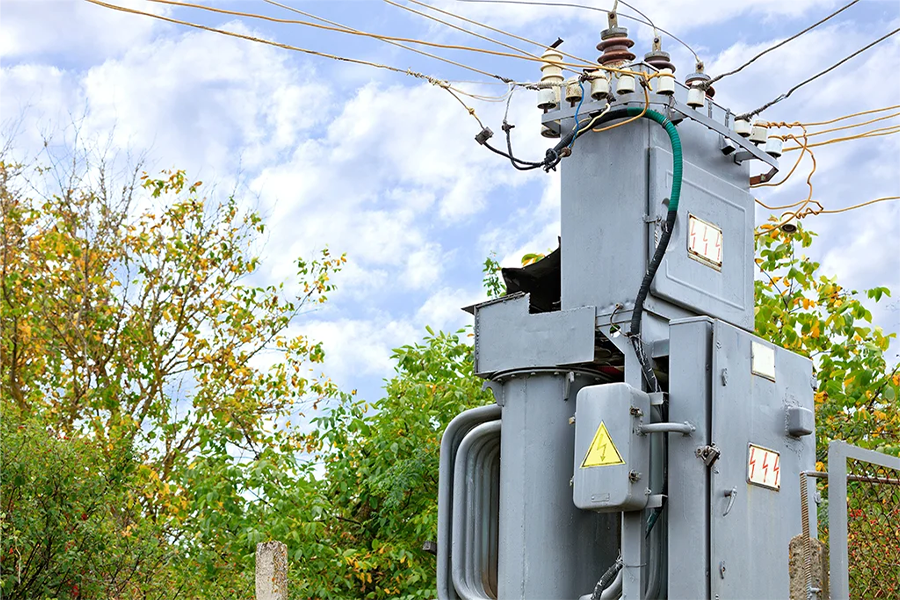
Current Transformer-CT
Current Transformers (CTs): An Overview
A Current Transformer (CT) is a critical sub-product within the Panel Components category designed to safely measure alternating current (AC) in electrical systems. By stepping down high primary currents to standardized, manageable secondary levels (e.g., 1A or 5A), CTs enable accurate monitoring, metering, and protection without direct contact with high-voltage circuits. They operate on the principle of electromagnetic induction, ensuring galvanic isolation between the primary (measured) and secondary (output) circuits.

What are Current Transformers?
A Current Transformer (CT) is a type of instrument transformer that converts high primary currents (e.g., hundreds or thousands of amps) into proportional, low secondary currents (typically 1A or 5A). This allows safe measurement and integration with meters, relays, and control systems. CTs are critical for:
Safety: Isolate measurement/protection circuits from dangerous high-voltage lines.
Accuracy: Provide precise current data for energy metering, load monitoring, and fault detection.
Compliance: Meet regulatory standards for electrical system monitoring and reporting.


Types of CTs
Metering CTs: High accuracy for energy billing and load monitoring.
Protective CTs: Robust design to withstand fault currents for relay/breaker coordination.
Summation CTs: Combine multiple currents into a single output for system monitoring.
Miniature CTs: Compact designs for panel-mounted or PCB integration in low-power systems.
Key Features
Current Ratio:
Defined as the ratio of primary to secondary current (e.g., 100:5). The secondary current is proportional to the primary current, scaled for safe measurement.
Common secondary outputs: 1A, 5A, or mA-level signals for modern low-power applications.
Accuracy Classes:
Measurement CTs: High precision (e.g., Class 0.1, 0.2, 0.5) for energy metering and revenue-grade applications.
Protection CTs: Designed to handle fault currents without saturation (e.g., Class 5P, 10P) for circuit breakers and relays.
Core Materials:
Laminated Iron Core: Used in protection CTs for high saturation thresholds.
Nickel Alloy or Amorphous Core: Found in measurement CTs for superior linearity and accuracy.
Safety & Isolation:
Provides galvanic isolation, protecting equipment and personnel from high-voltage hazards.
Complies with standards like IEC 61869, ANSI C57.13, and IEEE C57.13.
Form Factors:
Window-Type (Ring-Type): Installed around a conductor without disconnecting the circuit.
Bar-Type: A fixed primary conductor (bar) for high-current applications.
Split-Core: Hinged design for retrofitting onto existing conductors.
Rogowski Coils: Flexible, air-core CTs for transient or harmonic current measurement.
Burden Rating:
Specifies the maximum load (impedance) the CT can drive on its secondary without accuracy loss (e.g., 2.5 VA, 5 VA).
Types of CTs
Metering CTs: High accuracy for energy billing and load monitoring.
Protective CTs: Robust design to withstand fault currents for relay/breaker coordination.
Summation CTs: Combine multiple currents into a single output for system monitoring.
Miniature CTs: Compact designs for panel-mounted or PCB integration in low-power systems.
Applications
Energy Metering: Integrate with kWh meters for utility or submetering.
Protective Relaying: Trigger circuit breakers during overcurrent or short-circuit events.
Panel Instrumentation: Feed data to digital panel meters (DPMs) or SCADA systems.
Power Quality Analysis: Monitor harmonics, surges, or imbalances.
Renewable Energy Systems: Measure inverter output in solar/wind installations.
Advantages
Safety: Isolate users from high-voltage circuits.
Scalability: Measure currents from a few amps to thousands of amps.
Versatility: Compatible with analog meters, digital displays, and IoT-enabled devices.
Durability: No moving parts; long-term stability in harsh environments.
Critical Considerations When Selecting a CT
Primary Current Range: Match the CT’s rating to the system’s maximum and nominal current.
Accuracy Requirements: Choose Class 0.2 for billing vs. Class 5P for protection.
Physical Size: Ensure the CT fits the conductor or panel cutout (e.g., window diameter).
Burden Capacity: Avoid overloading the secondary with excessive impedance.
Environmental Conditions: Select CTs rated for moisture, temperature, or vibration.
Safety Notes
Never Open-Circuit a Live CT: A disconnected secondary can induce dangerous voltages. Always short-circuit unused CTs.
Grounding: Properly ground the secondary to prevent insulation failure.
Comparison with Voltage Transformers (VTs)
While CTs step down current, Voltage Transformers (VTs) step down voltage for measurement. Both are essential for comprehensive power system monitoring.
Conclusion
Current Transformers are indispensable in modern electrical panels, bridging the gap between high-power systems and safe, precise measurement tools. Their ability to isolate, scale, and protect makes them vital for energy management, equipment safety, and compliance with regulatory standards. When paired with Digital Panel Meters (DPMs), CTs form the backbone of intelligent, data-driven control systems across industries.

At United Force Trading Company, we proudly serve as an authorized Schneider Retail Partner, offering trusted power and control solutions .
